555 Timer Circuit Schematic : The good thing is that this chip could work directly with 12v so no driver for the mosfet is needed.. Here is the list of 40 555 timer circuits that can help you in understanding 555 timer functions.first five circuits explains. The 555 timer ic is an integrated circuit (chip) used in a variety of timer, delay, pulse generation, and oscillator applications. A 555 timer is a very versatile. If an led is placed at the output of this astable circuit, it will turn on at the same span of time as it is turned off. You can watch the following video or read the written tutorial below.
This is the schematic below for the 555 timer that creates one square wave output. Monostable 555 timer circuits will automatically trigger and start a timing cycle when power is applied to the circuit. How do i draw this schematic on latex? Si notation all the schematics in this ebook have. If an led is placed at the output of this astable circuit, it will turn on at the same span of time as it is turned off.
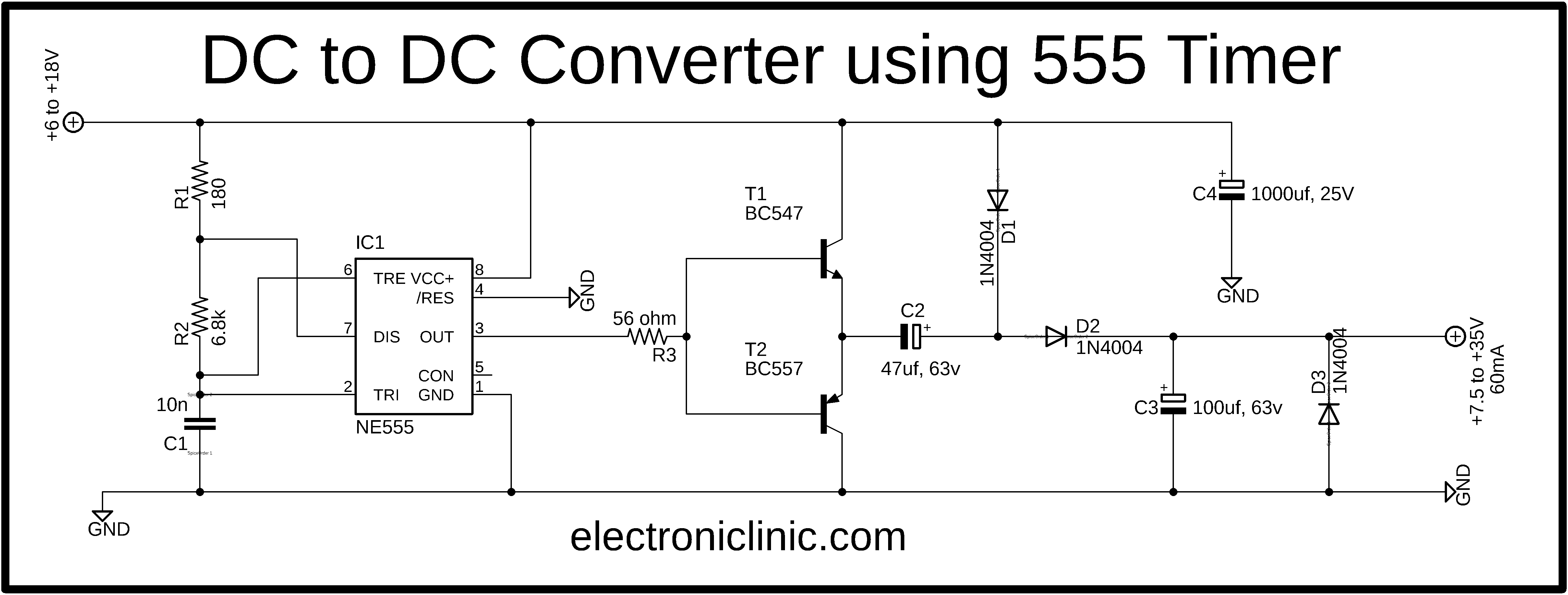
Simple Dc To Dc Converter Using 555 Time Ic 6v To 35 Volts Boost Converter from www.electroniclinic.com Frequency is 1000 hz then c2 will have greater benefit than if the oscillator frequency is 10 hz. The 555 timer is an integrated circuit, it is extremely versatile and can be used to build lots of different circuits. I used a 9v supply. Timer b in this method acts as a voltage comparator and has no timing function. The circuit layout is for a 555 timer in astable mode. Here is a code that can be used as a framework for your circuits, here is how to create new components and use them as if they were components in cad. You can watch the following video or read the written tutorial below. The 555 and 7555 are called timers or timer chips.
Taking apart a circuit board or module and reconstructing its complete schematic is a valuable skill.
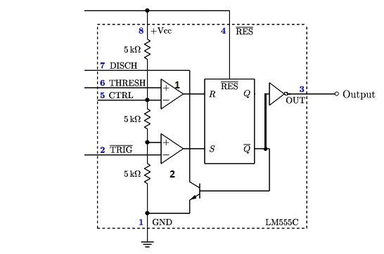
The breadboard schematic of the above circuit is shown below. We can see that it us made up of 21 transistors, 4 diodes, and 15. Astable mode can produce digital square waveforms that go back and forth between. Here is the list of 40 555 timer circuits that can help you in understanding 555 timer functions.first five circuits explains. The circuits explained here are 10 best small timer circuits using the versatile chip ic 555, which generates predetermined time intervals in response the image shown below represents the internal schematic of a standard ic 555. Since the project only involves assembling a simple circuit by following the schematic, it will only take an hour to make. Therefore, at low astable frequencies lm555 complimentary outputs schematic timer b in this method acts as a voltage comparator and has no timing function. The 555 and 7555 are called timers or timer chips. Learn about the 555 timer and how it works in astable mode. The schematic is shown in fig 5. It is a slave to timer. 7 below, you'll see the circuit schematic of the 555 and the parts relevant to it. The output of uc (upper comparator) which is reset input to rs latch is high when the threshold input is high or.
The timer generates an output pulse with an on time period determined by the rc network i.e t = 1.1rc. This 555 timer is in astable mode. We can see that it us made up of 21 transistors, 4 diodes, and 15. This tutorial provides sample circuits to set up a 555 timer in monostable, astable, and bistable modes as well as an in depth discussion of wiring info: A 555 timer is a very versatile.
555 Timer Ic Introduction Basics Working With Different Operating Modes from www.engineersgarage.com The output load is driven by the relay switch which is in turn controlled by the timer circuit. The 555 timer, designed by hans camenzind in 1971. Timer b in this method acts as a voltage comparator and has no timing function. Si notation all the schematics in this ebook have. And now a full schematic of the 555 timer oscillator with single step and free run option. Monostable 555 timer circuits will automatically trigger and start a timing cycle when power is applied to the circuit. How do i draw this schematic on latex? Generally, it's miles a monolithic timing generally, it's miles a monolithic timing circuit that offers unique and surprisingly stable delays of time or oscillation.
And now a full schematic of the 555 timer oscillator with single step and free run option.
Here is the list of 40 555 timer circuits that can help you in understanding 555 timer functions.first five circuits explains. The 555 timer ic is an integrated circuit (chip) used in a variety of timer, delay, pulse generation, and oscillator applications. The schematic is shown in fig 5. Taking apart a circuit board or module and reconstructing its complete schematic is a valuable skill. One configuration of this timer creates a perfect square wave. How do i draw this schematic on latex? With this information you will learn how how the 555 works and will have the experience to build some of the circuits below. Si notation all the schematics in this ebook have. The 555 timer shown above is configured as an astable circuit. So far i have tried drawing from this link which was supposed to produce. Generally, it's miles a monolithic timing generally, it's miles a monolithic timing circuit that offers unique and surprisingly stable delays of time or oscillation. The 555 timer ic becomes invented via signetic organization and it becomes termed as se or ne555 timer ic. This tutorial provides sample circuits to set up a 555 timer in monostable, astable, and bistable modes as well as an in depth discussion of wiring info:
The timer's internal circuitry is largely responsible for this. The output load is driven by the relay switch which is in turn controlled by the timer circuit. One configuration of this timer creates a perfect square wave. It is a slave to timer. So far i have tried drawing from this link which was supposed to produce.
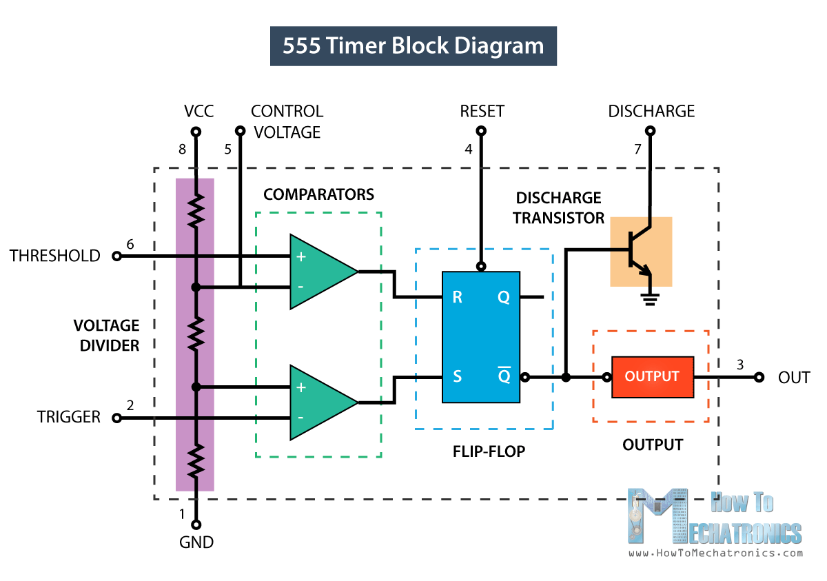
555 Timer Ic Working Principle Block Diagram Circuit Schematics from howtomechatronics.com Since the project only involves assembling a simple circuit by following the schematic, it will only take an hour to make. The 555 timer is an integrated circuit, it is extremely versatile and can be used to build lots of different circuits. The timer generates an output pulse with an on time period determined by the rc network i.e t = 1.1rc. And now a full schematic of the 555 timer oscillator with single step and free run option. The 555 timer is a simple integrated circuit that can be used to make many different electronic circuits. It is a slave to timer. The output of uc (upper comparator) which is reset input to rs latch is high when the threshold input is high or. Astable mode can produce digital square waveforms that go back and forth between.
The 555 timer is configured as a monostable multivibrator.
How do i draw this schematic on latex? I used a 9v supply. It is a slave to timer. Si notation all the schematics in this ebook have. The 555 timer can provide time delays ranging from several minutes for one cycle of operation to many. A better circuit is using a 555 timer. The red section is the. In this circuit, we will build a clock of about 60hz. The schematic is shown in fig 5. The timer's internal circuitry is largely responsible for this. To observe the 555 timer in astable mode, let's build a circuit that uses the 555 timer's oscillating output to make. This 555 timer is in astable mode. It's a simple source of oscillating in the schematic above, notice that the threshold pin and the trigger pin are connected to c1.
With this information you will learn how how the 555 works and will have the experience to build some of the circuits below 555 timer schematic. So far i have tried drawing from this link which was supposed to produce.


0 Komentar